Posts

DIY ELECTRONIC MICROSCOPE

Image
here is a project i made some time ago and currently using it for electronics inspection. if you're interested about more projects like this please subscribe to my channel

cheap regulator test AMS1117-5 are they any good??

Image
today in this video i'm testing a low dropout voltage regulator bought from e-bay.  the AMS1117-5 is a fixed voltage low dropout regulator and according to the datasheet can provide 5 volts output at 1amp max .the operating voltage is up to 15volts max. watch the video and please comment: is it worth buying or not? schematics of the circuit under test.

CHEAP VOLTMETERS TEST WITH AD584 MODULE

Image
  in this episode im testing various cheap voltmeters to see how accurate they are with a '' High Precision Voltage Reference Module '' bought from e-bay and based on AD584 ic by analog devices. then i'm trying to calibrate the ones that are out of specs.

ADJUSTABLE ELECTRONIC LOAD PROJECT

Image
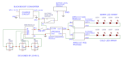
  in today's episode i will show you how i built an adjustable electronic load.at the end of the video im testing this unit with another great diy project,an adjustable power supply.Electronic loads are very useful for testing power sources. every serious hobbyist or technician should have one.for instance you can check a usb charger or a power supply if it can provide the current it claims or not. schematics   pcb components placement  if you cant understand how the components are placed on pcb you must download this file and install diptrace software to view it.

philips crt tv repair - common failure

Image
repair tip for the philips crt tv 14PT1332/01 CHASSIS L6.1AA. its a very common failure in these models and in other similar philips models too. i hope someone may find it usefull. sorry for the shaky video.it was last moments filming..

DIY UV EXPOSURE BOX - MAKE PCB'S @ HOME

Image
ultraviolet exposure device i built few months ago. it is controled by an arduino pro mini and has a 7 segment display to show the set and remaining exposure time. it uses ultraviolet leds(49 total)bought cheap from ebay. you can wire the arduino and the rest components using the diagram below.this way i made it too.you can connect any common cathode 7 segment display as long as you know witch pin is the segment shown in the diagram.or you can find it by applying about 3volts to each pin to see witch segment lits and write it down.(as i did)or downloading its diagram if exists.. then programm the arduino with the code given in the link below.you can skip the circuit with the mosfet and the optocoupler and connect a 5 volt relay as shown in the diagram(relay output & ground) to controll the leds. if you liked this project please subscribe to my channel for more future projects.... arduino code : https://drive.google.com/open?id=1SK-jNM7jZIcx-jIN8e3rleN_-12L9IQG

QUICK LOOK INSIDE ''ADS CD3'' VINTAGE CD PLAYER

Image
mini teardown of a working very old cd player by analog & digital systems inc. manufactured in january 1986.   and here are some photos...
Image
CAMCORDER DIY LED LIGHT WITH WARM - COLD ILLUMINATION ADJUSTMENT     VIDEO ABOUT THE CONSTRUCTION     very usefull diy led light with warm - cold adjustment perfect for filming videos.it consists of cheap & easy to find components and modules.it is powered of 18650 li-ion batteries and includes charging circuit. the illumination tone can be adjusted to warm - neutral or cold by two potentiometres. it uses a boost converter circuit to keep the output voltage stable for the leds so the light produced remains stable until the batteries are fully discharged. there is also a buck - boost converter for charging purposes that is adjusted to provide a constant current - voltage to charge the batteries.it can be powered from 5-25 volt and the current required is about 2amps. here are the components used...(search with these terms) 3W High Power cool/warm white 3000k 4000k 10000k-30000k LED + 20mm star pcb   AMS1117-ADJ REGULATOR CIRCUIT(build your own)

how to create pcb's at home - smd & through hole components soldering

Image
consider subscribing to this channel and help it grow to produce more quality videos schematics and pcb below

led tv backlight repair - led array repair

Image
in this video you can see how to replace a dead led from a led array bar of a led tv keep in mind that you should replace all led arrays with new but if the tv set has many led arrays and they are expensive to replace them all then this is the only way. just remember at the end to lower the setting for the backlight from the tv so the leds dont stress to much.

BUCK CONVERTER MC34063 (step down converter)

Image
another usefull circuit is the buck converter. A buck converter ( step-down converter ) is a DC-to-DC power converter which steps down voltage (while stepping up current) from its input (supply) to its output (load). here is a pcb that i designed using smd and through hole components for reducing the size of pcb. the only difference is that i used bc869 and not 2n5401 shown in schematics.  the output voltage can be adjusted by the trimm 20k.the pcb i designed uses a multiturn trimpot for higher precision.maximum output current is about 700ma.

simple on-off circuit

Image
with this simple circuit you can turn on-off a relay with 2 tactile buttons.

**** new youtube channel ***

Image
this is my new youtube channel where you can watch content about electronics,teardowns & repairs and project presentations electronics4all 

electronic on off switch with only 2 transistors

Image
the above circuit is a simple but very usefull electronic switch that allows you with a press of a tactile button to switch on or off a load.output current that the circuit can handle depends from the mosfet q2 you use. the circuit is ideal for small projects like a diy led flashlight that you dont want to use a mechanical switch and make it look more professional..i used it to make many flashlights and i designed a small pcb with smd components to fit around the tactile button so you can mount it directly to your project. transistor q1 is not critical and you can use any generic pnp transistor you have laying around. combined with a relay at the output you can make it to switch on-off the output of a bench power supply or an electronic load(i will publish both in the near future).in my tests it can operate from 3.5-25 volts again depending the q2 you are using. pcb and photos coming soon..... q1 can be replaced with:2N3906 - BC557 - BC857 and many more... q2 may be r